- Originates from deep vein thrombi (DVT's) found in legs
- DVT's break off, move through the venous system and become trapped in the lungs
- When injecting MAA particles, the particles cannot pass the area that has a PE
- Results in a cold defect when imaged with MAA
- Ventilation shows normal uptake since the activity is in the bronchioles (PE does not trap the airway)
- Key point - PE appears cold in perfusion and hot in ventilation (mismatched defect)
- Symptoms of PE
- Shortness of breath/air (SOA)
- Sudden onset of chest pain
- Dyspnea
- Cardiac arrhythmias
- Drop in the patient's PO2 level (normal 90-110)
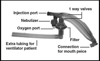
- Aerosol system
- Approximately 35 mCi of 99mTcDTPA is injected into the nebulizer (refer to diagram)
- O2 enters the nebulizer converting liquid (99m TcDTPA) into small liquid droplets
- The patient inhales and droplets coating the inside of the lungs
- The patient exhales and the remaining droplets and water vapor are trapped by the filter
- Note the one-way value in the diagram
- The system is shielded in a blue bucket
- Example of another aerosol system
- Below is a display of how a patient is dosed if he/she is on a ventilator. Extra tubing is added at the end of the system referred to as the "tail"
- Dosing the aerosol
- Usually, the patient breaths on this system five minutes
- After the ventilation process images are then taken at 150k counts per view or five minutes
- View may include: ANT, POST, LPO, RPO, LAO, RAO, LLAT, and RLAT
- This procedure is usually done before the Perfusion images (99mTcMAA)
- All images that are taken must match all the perfusion images taken (at the exact same angle)
- PE will show a mismatch defect(s) - hot in ventilation and cold in perfusion
- Usually, PE defects are segmental or subsegmental
- Usually, PE is multiple in occurrence
- COPD will show matched defect(s) - cold in ventilation and cold in perfusion
- Severe COPD will show clumping of the droplets in the lungs - "hot grapes" and may cause the study to be mis-read

Xenon Ventilation Procedure
Return to the beginning of the document
Return to the Table of Contents