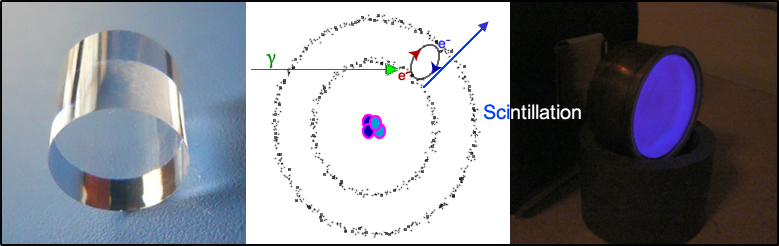
Basic Instrumentation

    1. Gas-filled detectors (see the above diagram)
      1. There are two basic types of detection devices that use "gas" (or air) to detect the presence of radiation: ionization (chamber or meter) and Geiger-Mueller (GM) meter
      2. When gamma-rays enter a gas detector it ionizes a molecule (loss of an electron)
      3. The applied high voltage (HV) is strong enough to cause ion pair to drift apart
      4. Atom goes to cathode side (-)
      5. Free electron goes to anode side (+)
      6. This event is then recorded on a rate meter as a "single" ionization event that was caused by a gamma-ray interaction
      7. These events are usually measured in mr/hr or cpm (usually recording in roentgen)
      8. There is a relationship between applied voltage, the number of ion pairs produced, and the recording of a gamma ray event within a gas filled chamber
    2. Depending on the degree of voltage applied, a certain number of ion pairs will be produced (see the above diagram). As HV increases, so do the amount of ion pairs
      1. If a gamma ray enters the system and there is no applied voltage, an ion pair will be created and then recombine without being recorded
      2. Region I (Recombination) - As you increase your applied voltage ion pairs are procedure and some recombine. As voltage increases less recombine and more of ion pairs make it to cathode/anode
      3. Region II (Ionization) - As this level of voltage one ion pair will be produced per each gamma recorded. What advantage/application do you see regarding the ionization region?
      4. Regions III/IV (Proportional and Non-Proportional) - As voltage increases, the amount of ion pairs produce continue to increase
      5. Region V (Geiger-Mueller) - As voltage continues to increase ion pairs generates many ion pairs (cascading occurs because of the excessive voltage in the gas). Reaching the GM region there is greater sensitivity in picking up radiation when compared to Ionization region Advantage/disadvantage?
      6. Region VI (Continuous discharge) - There is so much voltage that ion pairs are produced without any gamma ray causing continue discharge
    3. Ionization Chamber - dose calibrators and Cutie Pies
      1. One to one event
      2. Used in areas where there is a lot of radiation (less sensitive)
    4. GM meter
      1. One ion event causes a cascade event (many ionizations)
      2. Excess HV causes the cascade
      3. Used in areas where there is low or less radiation (more sensitive)
      4. Sensitive to <0.1 mr/hr
    5. Dose Calibrator
      1. Is an ionization chamber
      2. Reads activity in Curie to micro Curie (Ci to μCi) level or Becquerel (Bq)
      3. Used to determine the dose that will be administered to the patient
      4. Thinking dose calibrator .. Lots of activity in a syringe. It needs to be "less sensitive"
    6. Key point - Understand the application of a roentgen as it measures the intensity of radiation. Link

  1. Scintillation Device
    1. Collimator - will be discussed later (extrinsic)
    2. Aluminum (Al) shell and NaI(Tl) crystal (intrinsic)
      1. Al shell cover the crystal by three sides, leaving one end exposed to the PMT(s)
      2. Al offer little to no protection
      3. Can shield alpha and beta
      4. Has reflective properties and helps in the scintillation process
      5. It is air tight seal no moisture gets in and the crystal, hence it is hygroscopic and hermetically sealed - Should moisture get it would greatly alter the scintillation properties of the crystal
    3. Crystal is NaI contaminated with Tl - NaI(Tl) [intrinsic]
      1. Hygroscopic
      2. Tl improves the scintillation process
      3. Scintillation occurs when gamma energy is absorbed
        1. Gamma rays are absorbed by the crystal via Compton and Photoelectric
        2. Excitation of outer shell election causes election to move into a higher orbit
        3. Gamma ray returns to its normal orbit, it scintillates releasing energy in the form of light
        4. Short You Tube video shows scintillation when an x-ray interacts with the crystal

      Important - The entire process of recording a gamma event must be proportional - From scintillation to the end product (ex. counts)

  2. Photomultiplier Tube (PMT)
    1. Photocathode coverts light into electrons
    2. Goal is to create an electron pulse (lots of elections)
    3. As energy gamma increases, the amount of light increases causing more electrons to be released from the photocathode
    4. HV in the system pulls the electrons forward to the first dynode
    5. Each dynode doubles in the amount of electrons
    6. Electrons move through a series of dynode
    7. Each PM tube has between 10 to 12 dynodes
    8. PMT in action - https://www.youtube.com/watch?v=f61eMq4Wg4w
  3. As the amount of electrons increase a pulse height is generated and increases as well
    1. Pulse height
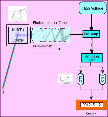
      1. Once light has been converted to electrons the purpose of our imaging system is to magnify the pulse height
      2. As the electrons move through the system, proportionally, the pulse height continues to increase
    2. Pre-Amplifier (Pre-Amp)
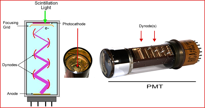
      1. PMT(s) are hard wired to the rest of the imaging/counting system
      2. Impedance is applied which slightly reduce the pulse height in order to prevent noise in the system
      3. Have you ever heard a "buzzing" sound coming from a sound system?
      4. What might that sound like? Link
      5. It does not amplify the pulse height
    3. Amplifier
      1. Pulse height reaches the amplifier, it will be amplified as much as 8000 times
      2. This generates a spectrum (of energy) that contains the energy from the gamma-ray(s) recorded from the initial scintillation of the crystal


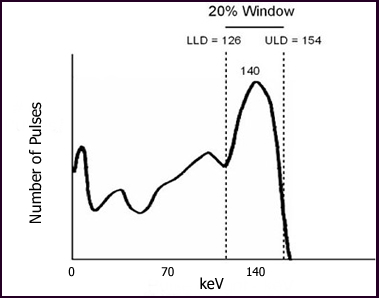
    4. Reading the energy peak - Pulse Height Analyzer (PHA) contains lower and upper level discriminators (LLD and ULD) are seen in the above graph
      1. LLD and ULD sets a window in which the pulse will be recorded or rejected
      2. Any pulse that is below the LLD is rejected
      3. Any pulse that is above the ULD is rejected
      4. Only the pulses that are between the LLD and ULD are allowed to continue through the system
      5. An electron pulse that falls within the LLD and ULD is recorded
      6. Diagram shows a window set at 20% around 140 keV gamma (99mTc)
      7. Calculate the LLD and ULD settings for a 140 keV gamma with a 20% window

      Step 1 - 20% / 2 = 10%

      Step 2 - Convert 10% to 0.1

      Step 3 - 140 * 0.1 = 14 keV

      Step 4 - Fourteen above the peak is (140 + 14 =) 154 keV is the ULD setting and fourteen below the peak is (140 - 14 =) 126 keV and that is the LLD

    5. Reading the gamma event
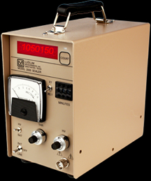
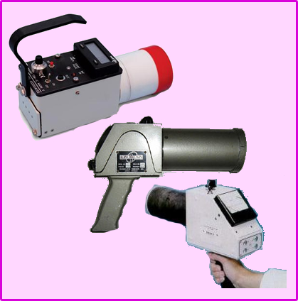
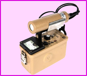
      1. The imagine above is known as a "scaler" device and it only records gamma events
      2. Usually recorded in counts per second (cps) or counts per minute (cpm)
      3. Can be set to preset time - Ex. How many counts were collected over 5 minutes
      4.  

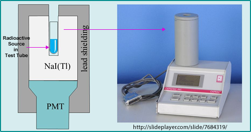
      5. When you collect gamma counts with a well counter a source of radioactivity is placed inside the chamber and the amount of radioactivity is recorded
      6. This device is also used to determine removable radioactive contamination, which is referred to as a wipe test
      7. Gamma camera records gamma events with a location of a x/y axis or 2-dementional (next lecture)

Return to the beginning of document
Table of Contents

Next Lecture - The Gamma Camera and Collimation

5/20