- PM tubes
- Each camera has a set of PM tubes
- The arrangement of tubes covers the entire surface of the crystal
- There maybe as little as 19 (old system) or as many as 91 or even more (current technology)
- Depending on where the gamma ray scintillates with the crystal, light will be given off and shared between the PMTs

- Diagram shows one gamma ray scintillating between four PM tubes - light is shared equally between the four PMTs
- Diagram also shows gamma ray scintillation occurring in the center of one PM tube. Here the majority of light is received by one tube
- As light energy is converted to electrons x/y coordinates are applied
- After the scintillation has been accepted by the PHA the data is stored and then recalled for display on a computer screen
- Acquired data is stored on a hard drive and then later displayed on a monitor for evaluation and/or image quantification
- Z pulse
- Think about this is a detector head has 90 plus PMTs all working together do you think there would be a slight different between their sensitivity to pick a scintillation event?
- Z pulse corrects for this variation
- To make this work the sensitivity of all the PM tubes in the imaging field must acquire data in an equal fashion
- Failure to correctly adjust the PMTs would cause an abnormal collection of data, generating cold or hot spots that are really not there
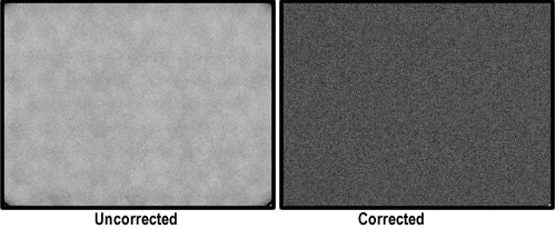
- Here is an exam of a correct and uncorrected flood source where there is an equal amount of radiation being exposed to the entire surface of the detector head
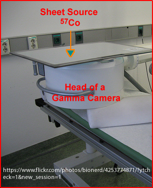
- Therefore system uniformity is critical when collecting data. To assure system uniformity data is collected from a uniform source of radioactivity - the example here uses a 57Co sheet source
- To improve system uniformity a Z pulse is applied. It will compensate for a PMT's variation in collecting data, either remove or add counts from each PM tube within the detection area of each PMT. Here is one method in which counts are corrected:
- Subtracting counts increases the time of collecting imaging, but is considered the "true" counts
- Adding counts decreases imaging time, but it adds counts that are not really there
- In order to determine how many counts should be subtracted or added a uniformity matrix flood is collect which ranges between 30 to 120 million or more counts
- Average counts are determined for each PMT and the Z pulse then corrects the acquisition
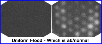
- Here are two examples of a uniform flood. Houston, "What seems to be the problem."
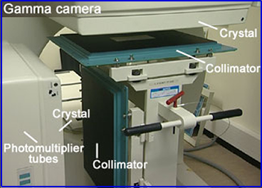
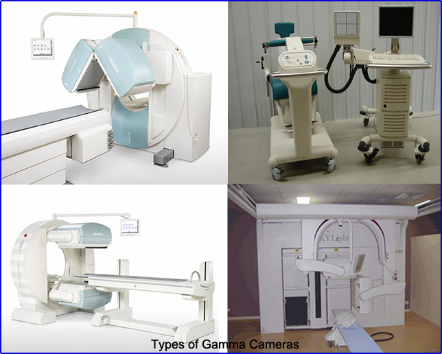
- Here are several types of gamma cameras
- Collimators
- On the surface of crystal a collimator is placed to "focus" the incoming gamma
- A collimator is made up of septa which are composed of lead
- Incoming gamma that fails within the "field of view" interacts with the crystal (see diagram)
- If an incoming gamma falls outside its "field of view," the gamma will encounter a lead septa
- Septa will absorb all the energy of the gamma ray or
- Septa will absorb part of the energy reducing the keV of the incoming gamma ray causing it to fall below the LLD
- Counts that fall below the LLD are will be rejected
- Considering the size of a septa
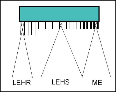
- Septa that are short in length allow a greater amount of gamma rays and improve sensitivity (increase counts) - This type of collimator is call High Sensitivity (HS)
- Septa that are longer in length allow less gamma rays and improve resolution but reduce counts - defined as High Resolution (HR)
- In general, the relationship between HS and HR is inversely proportional - you cannot have HS and HR in a collimator
- However, a collimator known as General All Purpose (GAP) scarifies both sensitivity and resolution
- Closer look to septa and how they are made - http://www.nuclearfields.com/collimators-nuclear-medicine.htm
- Considering the thickness of a septa
- Thinner septa with higher energy gammas cause septal penetration of the gammas, it crosses over and interact with the wrong area of the crystal and are recorded. This is referred to as cross talk. You do not want this type of data
- Therefore, septa thickness must increase as the energy gamma increases in order to prevent cross talk from occurring
- Low Energy (LE) septa have a range of 100 - 200 keV
- Medium Energy (ME) septa have a range of 200 - 300 keV
- High Energy (HE) septa have a range of 300 or greater keV
- Hence, collimators are classified as LE, ME, or HE
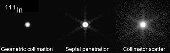
- Scatter and septal penetration from a point source of 111In
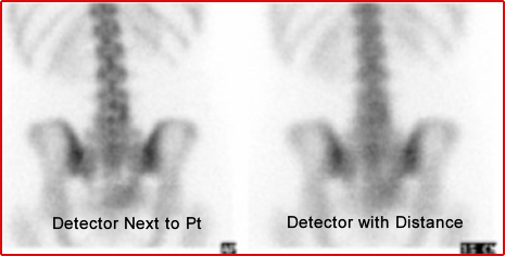
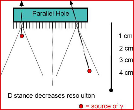
- Distance of the collimator/detector (camera head) to the patient is another critical component
- The closer the camera head is to the patient the better the resolution
- The further away from the camera head is from the patient a greater the loss of resolution. Why? See below
- Distance increases the amount of scatter resulting in a "fuzzy" image
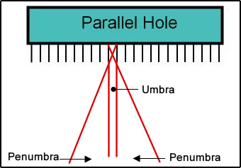
- Consider the incoming gamma ray and the septa's umbra and penumbra (refer to diagram)
- As the distances increases, the angle of the penumbra increases
- Draw a straight line from the septa, that is the umbra and the angle of true counts
- However, gamma rays that fall within the penumbra are recorded
- Therefore the greater the distance, the greater the penumbra, and the greater the amount of scatter counts
- The result is increased scatter and a loss of resolution as seen in the image above
- Therefore, when imaging the patient make sure the camera's detector is as close as possible - This improves resolution!
- Types of collimators
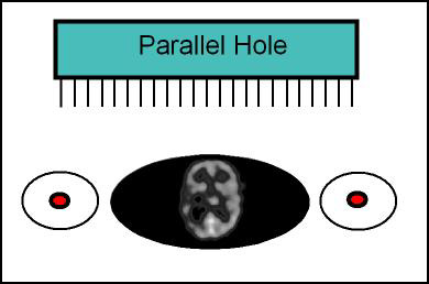
- Parallel hole (see diagram)
- Most common
- Septa are perpendicular to the surface of the detector
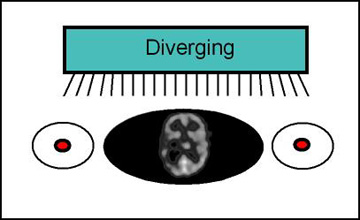
- Diverging (see diagram)
- Used to image an area that is larger than the camera head
- Septa are angled outward
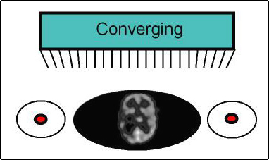
- Converging (see diagram)
- Used to magnify or enlarge the field of view
- Septa are angles inward
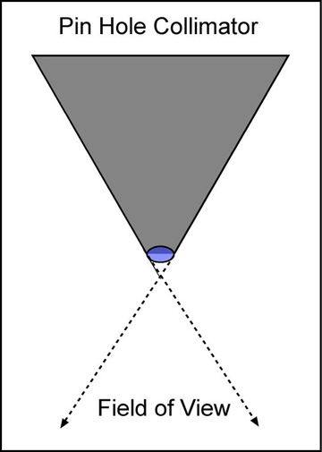
- Pinhole (see diagram)
- Used to magnify a very small area (ex. thyroid)
- Only has one small opening at the end of the collimator
- Works like a magnifying glass
- Flips it (rotates 1800)
- Resolution is very high and sensitivity is very low
- Changing a LEPH collimator
- Notice that there are two detector heads that need to be changed
- Parts of the gamma camera are identified
Extrinsic (prior to crystal) factors to consider when imaging
- Review of collimator characteristics
- High Sensitivity (HS), High Resolution (HR); or General All Purpose (GAP)
- Low Energy (LE); Medium Energy (ME); or High Energy (HE)
- LE - Energy gammas of less than 200 keV
- ME - Energy gammas between 200 and 300 keV
- HE - Energy gammas greater than 300 keV
- Parallel, diverging, converging, pinhole
- From the above options for collimation consider the following characteristic a septa must have
- Length
- Angle
- Thickness
- Also consider the effects of distance between the camera head and the area to be imaged
Applications of computers - Doing this semester you will also see the application of computers. As we discuss the different types of imaging procedures you will note their use in: acquisition, display, and in the quantification of patient data.