Part II Instrumentation - The Gamma Camera
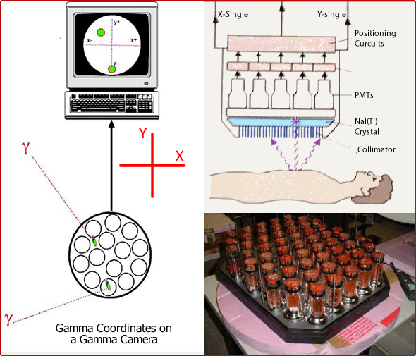
- Each camera has a set of PM tubes
- The arrangement of tubes covers the entire surface of the crystal
- There maybe as little as 19 (old system) or as many as 91 or more tubes (current technology)
- Depending on where the gamma ray scintillates with the crystal, light will be given off and shared between the PMTs
- Diagram shows one gamma ray scintillating between four PM tubes - light is shared equally between the four PMTs. The positioning circuits then define its location via the light shared
- Diagram also shows gamma ray scintillation occurring in the center of one PM tube. Here the majority of light is received by one tube, which the positioning circuits identify
- As light energy is converted to electrons x/y coordinates are identified
- After the scintillation has be accepted by the PHA the data is stored and then recalled for display on a CRT screen
- Usually there are 100,000 plus counts recorded, giving definition of the are being imaged
- Consider a similar situation with a regular camera. The greater the aperture opening the more light enters
- Other devices also record data and may include: formatter (that has film), and monitor or p-scope (for immediate visual display)
- All PM tubes vary slightly in its sensitivity to pick up the scintillation
- Z pulse corrects for this variation
- To make this work the sensitivity of all the PM tubes in the imaging field must be equal
- Failure to correctly adjust the PMTs would cause an abnormal collection of data and a loss of uniformity. If you collect data from a uniform source of activity then a uniform flood is seen below (left image) However, if the PMTs' Z pulse is off you might see abnormal distribution of activity (right image)
- When the Z pulse is being used the system with either remove or add counts from each PM tube in order to get an even distribution of counts across the entire crystal
- Subtracting counts increases the time of collecting imaging, but is considered the "true" counts
- Adding counts decreases imaging time, but it adds counts that are not really there
- In order to determine how many counts should be subtracted or added a uniformity matrix flood is collect which ranges between 30 to 120 million or more counts
- Data is stored and Z pulse can be determined for each PM tube
- Here are two examples of a uniform flood. Houston, "What seems to be the problem."
- Types of gamma cameras


- On the surface of crystal a collimator is placed to "focus" the incoming gamma
- A collimator is made up of septa which are composed of lead
- Incoming gamma that fails within the "field of view" (umbra) interacts with the crystal at the appropriate keV (see diagram)
- If an incoming gamma falls outside its "field of view," the gamma will encounter a lead septa
- Septa will absorb all the energy of the gamma ray, or
- Septa will slow down the gamma ray, reducing the keV resulting in pulse height that falls below the LLD
- Counts that fall below the LLD will be rejected
- Considering the size of a septa
- Septa that are short in length allow for greater amount of gamma rays to be detected because the umbra is larger (see LEHS). Sensitivity improves, but at a cost to resolution) - Known as High Sensitivity (HS)
- Septa that are longer in length allow less gamma rays are detected (smaller umbra). This improves resolution (reduce counts) - known as High Resolution (HR)
- In general, the relationship between HS and HR is inversely proportional - you cannot have HS and HR collimator
- However, a collimator known as General All Purpose (GAP) scarifies both sensitivity and resolution
- Closer look to septa - http://www.nuclearfields.com/collimators-nuclear-medicine.htm
- Considering the thickness of a septa
- Thinner septa with higher energy gammas cause cause septal penetration of the gammas, it crosses over and interact with the wrong area of the crystal and are recorded. This is referred to as cross talk
- Therefore, septa thickness must increase as the energy gamma increases, in order to prevent cross talk from occurring
- Low Energy (LE) septa have a range of 100 - 200 keV
- Medium Energy (ME) septa have a range of 200 - 300 keV
- High Energy (HE) septa have a range of 300 or greater keV
- Hence, collimators are classified as LE, ME, or HE
- Distance of the collimator/detector (camera head) to the patient
- The closer the camera head is to the patient the better the resolution
- The further away from the detector is from the patient the greater the loss of resolution. Note how the red dot on the left is seen in the right location whereas the dot on the right gets recorded on the wrong location
- This is referred to as scatter radiation
- Consider the incoming gamma ray and the septa's umbra (refer to diagram)
- As the distances increases, the angle of the umbra increases
- Draw a straight line from the septa, and compare the angle of the umbra. Gamma rays that are within the umbra are recorded
- The initial location of the emitting gamma and the distance between the source of the gamma ray and the detector become very important in attaining image quality
- Therefore, when imaging the patient make sure the camera head is as close as possible - This improves resolution!
- Types of collimators
- Parallel hole (see diagram)
- Most common
- Septa are perpendicular to the surface of the detector
- Diverging (see diagram)
- Used to image an area that is larger than the camera head
- Septa are angled outward
- Converging (see diagram)
- Used to magnify or enlarge the field of view
- Septa are angles inward
- Pinhole (see diagram)
- Used to magnify a very small area (ex. thyroid)
- Only has one small opening at the end of the collimator
- Works like a magnifying glass
- Inverts the incoming image (L to R)
- Flips it (rotates 1800)
- Resolution is very high and sensitivity is very low
- Changing a LEPH collimator
- Notice that there are two detector heads that need to be changed
- Parts of the gamma camera are identified


http://dspace.jorum.ac.uk/xmlui/bitstream/handle/10949/961/Items/S809_1_section9.html
- Review of collimator characteristics
- High Sensitivity (HS), High Resolution (HR); or General All Purpose (GAP)
- Low Energy (LE); Medium Energy (ME); or High Energy (HE)
- LE - Energy gammas of less than 200 keV
- ME - Energy gammas between 200 and 300 keV
- HE - Energy gammas greater than 300 keV
- Parallel, diverging, converging, pinhole
- From the above options for collimation consider the following characteristic a septa must have
- Length
- Angle
- Thickness
- Also consider the effects of distance between the camera head and the area to be imaged