- Electronic artifacts can appear in a flood phantom in which images of computer board, lines, circles or half-circles appear. If the electronic appearance embeds itself into acquired patient data, this would create electronic artifacts on the acquired study
- Artifacts may also occur when there is non uniformity in the detector, which may be do to: PMTs fail, correction matrix problem, or even a cracked crystal
- Any artifact seen in a planar image is significantly enhanced when SPECT acquisition occurs. Consider the artifact being multiplied the amount of times acquired in an exam
- Upward creep occurs when the heart has moved downward into the chest cavity during stress. Once exercise has stopped, the heart slowly moves back up into its "resting" position within the thoracic cavity. This is known as upward creep. Acquisition of cardiac data should only start after the heart has moved back into its resting position.
- Issue -Consider the heart move between 2 to 8 pixels during the acquisition process a a false positive defects occurs in the myocardial wall
- Issue - heart moves 1 to 2 pixels a defect can be seen in anteroseptal defect
- Prevention - Start acquisition 5 to 15 minutes post exercise
- Usually upward creep is not a problem with 99mTc-cardiac agents, however, 201Tl may present a problem because the longer you wait prior to imaging the greater the amount of redistribution can occur. So when it comes to thallium do you wait? What would happen if an ischemic area filled in within 15 post exercise?
- General comments on soft-tissue attenuation
- Consider the type of radiopharmaceutical and its associated energy levels. The difference between 201Tl and 99mTc? How is attenuation affect between the two types of radiotracers?
- Factors that can influence a scan, causing attenuation are as follows: weight vs. height; chest size; breast size; fat on the lateral chest wall; and objects attenuated from the surface of the patient, such as objects worn around the neck or material left in the pocket
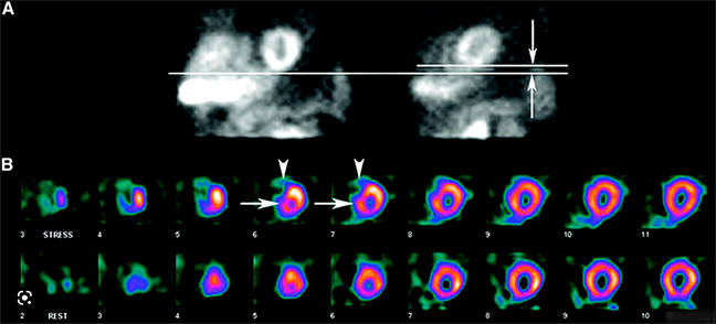
- Breast Attenuation
- Attenuation may cause defects in the anterior, anterolateral, and anteroseptal walls
- Defects my appear reversible if the breast is not in the same position during stress and rest acquisition
- The above image are examples of breast attenuation seen more on the rest images than on stress. The defect is in the anterioseptal wall as indicated by the arrow
- This type of defect cannot not prevented, but should be realized during the acquisition and processing of the procedure.
- Suggestions:
- Note the size of the patient breast and its "angle" during acquisition
- Imaging with the bra on or off is not essential, however, maintain the same type of imaging parameters for both stress and rest procedures
- Play back the raw data to see if breast shadow is present
- Observe the gated stress procedure and note attenuation vs. myocardial thickening
- If transmission imaging is available, use it
- Lateral chest wall fat attenuation
- Excessive fat maybe present. This causes attenuation defects
- Defect is seen fixed in the lateral wall and is similar to breast attenuation
- Suggestions
- Note the size of the patient's chest
- Evaluate the raw data to see if there are attenuation defects
- Observe the gated stress procedure and note attenuation vs. myocardial thickening
- Diaphragmatic attenuation
- Attenuation usually appears fixed in the inferior wall and is more common in patients that are: obese, have ascites, on dialysis, and/or male
- Defect is usually seen in the inferior wall and fixed
- Suggestions
- Note the attenuated area on the raw data (above the myocardium) by evaluating the raw data
- Observe the gated stress procedure and note attenuation vs. myocardial thickening
- Image the patient in the prone position usually removes this defect
- Excess activity by the heart
- Consider what happens if activity anywhere around the myocardium has a higher count rate when compared to the heart wall. Activity is drawn away from the myocardial wall making it appear as if there is defect (that really isn't there). Remember your SPECT physics?
- Liver, bowel, and gal bladder may cause this defect when injecting 99mTc-cardiac agents. As noted below the vertical long images show excessive bowel activity that indicates a defect in the inferior wall
- Suggestions
- Observe activity in and around the myocardium prior to acquiring the data. If excess activity is seen administer cold water or a fatty meal prior to imaging
- If excessive activity is noted below the myocardium, "gut activity," then shield it!
- Always look at the raw data to see if there is any interference
- Patient motion
- If the patient moves more than 0.5 pixels during the exam misalignment the reconstructed images may show an artifact. The greater the movement the more the artifact
- While the cine is not above is not available the static images demonstrate patient movement. Furthermore a defect generates an anterioseptal artifact
- Once the acquisition has been completed it is imperative that the technologist review the raw data to determine if there is any movement. The example above shows patient movement, however, slight it occurs in the middle of the rotating cine. This type of patient movement is sometimes blamed on the acquisition between two detectors (because it occurs in the middle - detector 1 ends and detectors 2 starts). Therefore, movement may be the results of the detectors and not the patient. What should the technologist do to determine if this is a instrumentation error?
- Sinograms and linograms indicate patient movement and is usually displayed with the raw data. If the "sino/linogram" shows a smooth line then the patient has not moved. However, an uneven line, broken line, or even an abnormal looking pattern in the sinogram and/or linogram indicates movement. Movement may also occur in either the vertical or horizontal plans. If sinogram looks abnormal then movement has occurred in the horizontal direction. Linograms evaluate the vertical direction.
- The type of artifact created during reconstruction depends on the amount of movement and when it occurred during acquisition
- Hypothetically it is better to have less movement at the beginning or end of the acquisition cycle, because movement during the middle of the exam heightens the defect
- Why have a rejection window with SPECT gated cardiac?
- Abnormal heart rate will cause difficultly in the gated process. As seen below the histogram of the "R to Rs" starts at 70 and goes to 170 bpm. LInogram and sinogram data also look irregular which again is due to drastic variation of the R waves
- Raw data may also show pixels flashes in the cine. If the raw data is processed then two abnormalities may occur: falsely low ejection fraction and reduced contractility
- So what happens if you process data that has patient motion? The example noted below shows what is known as the hurricane sign, the smearing of anterior and inferior walls. This occurs because the acquired pixels are not in the same three dimensional plane
- Suggestions
to prevent patient movement
- Make the patient as comfortable as possible to include head and knee supports
- Explain the exam completely stressing the reason not to move during acquisition
- Don't talk or have the patient talk during the imaging
- Keep someone in the room to observe any possible patient movement
- Following acquisition evaluate: the raw data; sinogram, and linogram for any movement
- Note - the LV must always be in the same plane when evaluating the cine
- If movement is noted, use motion correction software. If this fails, re-image the patient
- There are several other factors that might affect your reconstruction efforts on a SPECT cardiac exam
- Left or right bundle branch block can cause a reversible septal defect. The physician who is interpreting the exam should be made away of this. Also pharmacological stressing is preferred with these types of patients
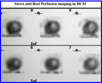
- Hypertrophic cardiomyopathy results in increased uptake in the Septal wall (due to excess muscle tissue) that may create falsely lateral wall defects (excess activity). In any case, the image below looks extremely abnormal
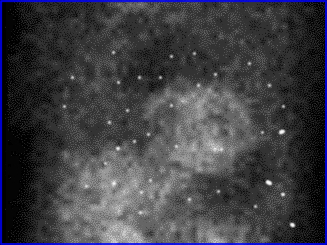
- Dextrocardia situs inversus (see above) occurs when this genetic abnormality reverses all the organs in the body, hence the heart is on the opposite side. Should this happen consider the following:
- Change acquisition parameters to 45 degree LAO to 135 degree RPO
- Defect is usually seen in the lateral wall, but is considered normal and represents the interventricular septum
http://emedicine.medscape.com/article/348503-imaging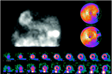
http://tech.snmjournals.org/cgi/reprint/34/4/193
Return to the Beginning of the Document
Return to the Main Menu
3/23