2.1 Before you start the simulation, you will need to create
a model file for the transistor with the Spice model parameters in it.
Use the text editor to open a file called VN2222LLB.sp in the same
directory where the circuit1 design is located and add the following
lines to it:
.MODEL VN2222LLB NMOS
+ LEVEL=1
+ VTO=2.3
+ KP=106U
+ GAMMA=0.4
+ PHI=0.37
+ LD=0.1U
+ LAMBDA=0.0108
Save the file and exit the test editor.
2.2 Start Accusim on your circuit1 design:
>> accusim circuit1 &
2.3 Use the File->Auxiliary Files->Load Model Library... file menu
item to bring up the Load Model Library dialog box. Use the Navigator...
button to bring up the File Navigator dialog box and select the
VN2222LLB.sp
file. Click OK in both dialog boxes.
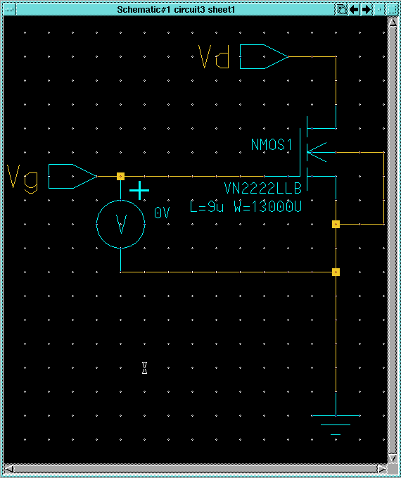
2.4 Select the Vd node in the schematic and use the Setup->Analysis...
menu item to bring up the Setup Analysis dialog box.. Setup a DC
sweep with Vd going from 0V to 5V and click OK.
2.5 Use the Setup->Results->Define Waveform menu item to bring
up the Define Waveforms dialog box. Create a new waveform called
Id
that is equal to the current going into the drain of the NMOS transistor.
Click Close in the Define Waveforms dialog box.
2.6 Use the Setup->Keeps...->Keeps... menu item to bring up the
Add
Keeps dialog box and click OK to add the default keeps on schematic
items.
2.7 Select the 0V voltage source on the schematic and use the Run->Sweep
Runs->Property on Instance... menu item to bring up the Sweep Property/Variable
dialog box. Click on the Select Property... button and select the
instpar=0V
property in the dialog box that comes up and click OK. Set
the From item to 1.8, the To item to 3.4, and
the Step item to 0.2 and click OK in the
Sweep
Property/Variable dialog box to start the simulation.
2.8 Use the Report->Waveforms menu item to bring up the Report
Waveforms dialog box. Click on the top-most ../../results item
(probably "/col/run/results (Default)") and click OK.
Scroll to the bottom of the results window that comes up and click on the
W(Id)
item to highlight it.
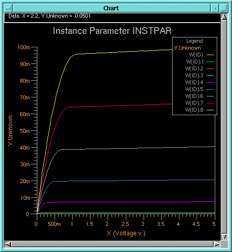
2.9 Use the Result->Chart->Family of Curves menu item to bring
up the Chart Signal from Collection dialog box. Notice that the
Signal
item is already filled out with the Id waveform we defined earlier.
Click on the Choose Collection... button and make sure that the
sweep
(DCOP) collection is selected in the dialog box that pops up and click
OK. Leave the Reference item blank in the
Chart Signal
from Collection dialog box and click OK in it. The result should
be a new chart window like the one below:


