1.1 Make a new directory for your diode simulations:>> cd egre224
>> mkdir lab2
>> cd lab2
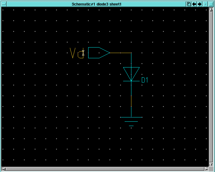
1.2 Start Design Architect to create the schematic of the circuit for this tutorial:2. Simulate your diode circuit to extract the Id vs. Vd curve with Accusim>> da &1.3 Use your knowledge of DA to create a new component called diode1 and construct a schematic for it using generic analog parts that looks like the one below:
Note that the portin and ground components come from the Generic Parts library under the MGC Analog Libraries palette. To find the 1N270 diode, from the MGC Analog Libraries palette, select the AccuParts library. From the AccuParts palette, select the Diodes library. From the Diode_Lib palette, select the button next to the 1n395 item. Scroll down until you find the 1n270 item in the Diode1 palette.
1.4 Check and Save your schematic and exit DA.
1.5 Create a simulation viewpoint for Accusim for the diode1 circuit with DVE as you did in the previous labs.
3. Generate tabular data from your simulation run2.1 Start Accusim on your diode1 circuit:>> accusim diode1 &2.2 Select the Vd node in the schematic and push the button. Setup a DC sweep with Vd going from -1V to 1V and click OK.2.3 Use the Setup->Results->Define Waveform menu item to bring up the Define Waveforms dialog box. Create a new waveform called Id that is equal to the current going into the anode of the 1N270 diode. Click Close in the Define Waveforms dialog box.
2.5 Use the Setup->Keeps...->Keeps... menu item to bring up the Add Keeps dialog box and click OK to add the default keeps on schematic items.
2.6 Click the button to run the simulation.
2.7 Use the Results->Chart...->Chart/Trace Defined Waveforms to open a trace of Id. The result should be a Chart window like the one below:
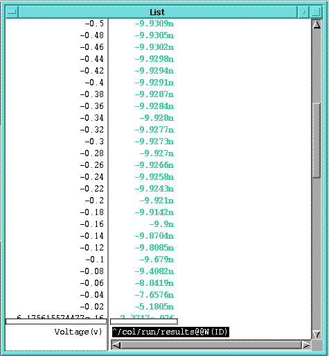
4. Simulate a diode with a Spice model file3.1 In the chart window, place the cursor over the W(ID) item in the Legend box and click the LMB. This should highlight the W(ID) item with a grey selection box.3.2 Click the button in the palette. This should result in a list window like the one below with tabular data of Id vs. Vd.
3.3 With the List window still active, use the File->Write... menu item to bring up the Write Report dialog box. In the Pathname item, enter simulated.txt as the name of the report file to generate.
3.4 Exit the Accusim tool.
3.5 Use the Text Editor in CDE to open the simulated.txt file. Go to the bottom of the file and take out the last line " Voltage(v) ^/col/run/results@@W(ID)". Use the Edit->Find/Change menu item to find all of the "m" characters in the file and substitute "e-3" for them. Likewise, change all of the "u" characters to "e-6", "n" characters to "e-9", "p" characters to "e-12", and "f" characters to "e-15".
3.6 Save the simulated.txt file and exit the text editor.
4.1 Use your knowledge of DA to construct another design called diode2 that looks like the one below:
This time, use the diode from the Generic Parts library under the MGC Analog Libraries palette.
Be sure to change the ASIM_MODEL property on the diode to D1 as shown.4.2 Check and Save the sheet and exit DA.
4.3 Create a simulation viewpoint for Accusim for the diode2 circuit with DVE as you did in the previous labs.
4.4 Use the text editor to create a file called diode_model.sp in the directory where the diode2 component is located. The file should have the following contents:
.MODEL D1 D IS=10.0P RS=10.0 N=1.04.5 Start Accusim on your design. Use the File->Auxiliary Files->Load Model Library... menu item to bring up the Load Model Library dialog box. Click on the Navigator... button and select the diode_model.sp file you just created. Click OK in the Load Model Library dialog box.4.6 Simulate the diode2 circuit just as you did the diode1 circuit above. Save the tabular data in a text file named simulated2.txt.