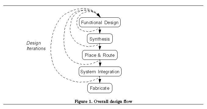
Synthesis is the process of
mapping the VHDL behavioral models into logic gate implementations. In
this design flow, synthesis is performed using the Leonardo Spectrum
tool from Exemplar that is part of the Mentor Graphics tool set. Leonardo
Spectrum is a synthesis tool which can target FPGA implementations.
It accepts either VHDL or Verilog as its input and generates and output
which consists netlist of library parts in the chosen technology, in this
case the Actel ACT1 family. The output netlist format can be either EDIF
(Electronic Design Interchange Format) VHDL, Verilog, or XNF (a netlist
format specifically for Xilinx FPGA tools). For this design flow, the EDIF
output format will be used as this is easily imported back into the Mentor
Graphics environment.
One of the keys to the synthesis
process, of course, is to write synthesizable VHDL models in the beginning,
as part of the functional design process. Because VHDL is a high level
language, it contains a number of complex constructs and allows modeling
in various styles (such as recursion) which are meaningless in terms of
an actual hardware implementation, and therefore are not synthesizable.
Fortunately, the Renoir tool generates synthesizable code for state
machines, so all that is necessary is to ensure that the behavioral descriptions
that are written by hand for the random logic blocks are synthesizable.
Most simple behavioral VHDL descriptions are in fact synthesizable, but
there are a number of books and references on writing synthesizable VHDL
including the HDL Synthesis Guide that describes the VHDL subset and coding
style that the Leonardo Spectrum tool accepts. This reference should
be consulted if any questions on the synthesizability of a VHDL model by
Leonardo
Spectrum arise.
Once the VHDL code is synthesized
into a gate level implementation in terms of Actel library parts, it must
be reimported into the Mentor Graphics environment for verification by
simulation and for export to the Actel toolset. Actel provides a tool,
called edn2mgc , that takes the EDIF netlist output by Leonardo
Spectrum , and creates a design in the Mentor Graphics database format
that is suitable for inclusion in a schematic within Design Architect
, and for simulation with Quicksim . Since this is just a netlist
format with no internal schematic, it is not possible to view the internal
structure created by the synthesis tools, or to trace internal signals
within the synthesized block during simulation. Normally, it is not necessary
to do this, but it the designers wants to, he or she can use the Mentor
Graphics schematic generator tool to generate an actual schematic for the
synthesized block before incorporating it back into the overall design.
After the VHDL blocks are synthesized,
new symbols for them must be generated (since they are schematics now,
not VHDL models) and a new overall RTL level schematic must be created
that has the synthesized blocks in place of the VHDL models. An easy way
to do this is to save the old RTL level schematic that included the VHDL
models, under a new name, and edit it to remove the VHDL blocks and replace
them with their synthesized equivalent. Once this schematic is created,
the entire design will be in terms of Actel library parts. It is wise at
this point, to functionally simulate this design again to ensure that it
is correct before the place and route function is performed. For this simulation,
the presimvpt tool is used again to prepare the proper unit delay
viewpoint, and the Quicksim simulator is used for simulation. Figure
4 shows the design flow for the synthesis step.


